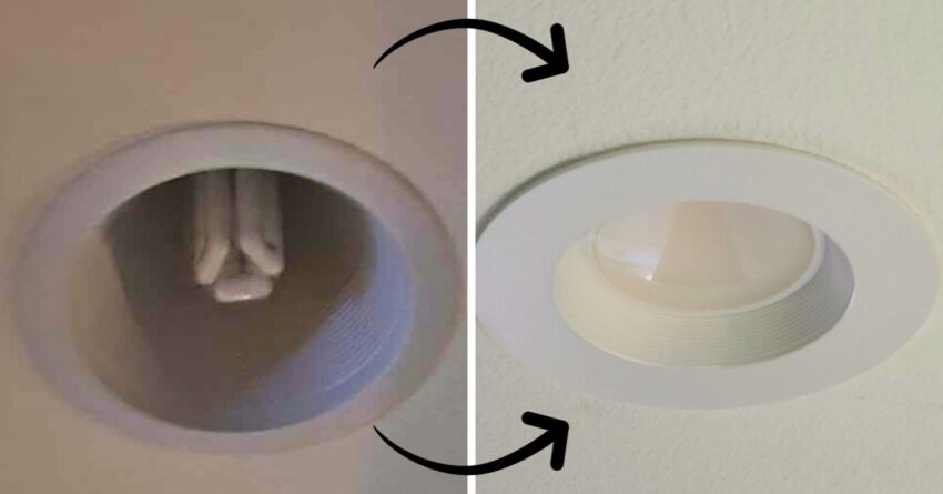
Z-Wave incompatability with CFL Ballasts
A large part of my never ending list of home projects is making (almost) everything “smart.” This requires converting 4-pin CFL to LED. Nine years ago, I started on a Z-Wave journey, and have been adding to it ever since. I’ve been converting our switches and outlets to Z-Wave devices. These devices can be controlled by Home Assistant.
Most Z-Wave switches cannot be used on CFL lights with ballasts. Coincidentally, almost every light in our house is (or was) a CFL. So, I set out on the journey of converting all of our 4-pin CFLs to LEDs. I ordered these Sunco LED retrofit lights from Amazon.
Bypass the Ballasts when converting 4-pin CFL to LED
Luckily, the actual conversion process is very easy to do. It’s just time consuming. For the first few lights, each rewire took me about 45 minutes to an hour. As I got better at it and more used to what I needed to do, I started being able to do each light in around 20-30 minutes.
A CFL ballast converts regular 120V electricity to a voltage that can be used by the CFL bulb. The LED we’re converting to uses the regular 120V wiring from the electrical panel. So, we’ll need to cut out and bypass those ballasts and wire the line voltage into the can, so that we can connect it to the LED lights.
TURN OFF THE POWER
The very first thing we need to do before accessing any of the wiring in the ceiling is turn off the power at the breaker.
Remove the Can for converting 4-pin CFL to LED
Now, we need to remove the can in order to access the ballast. Start by pulling the shroud down and out of the way, exposing the actual can housing. The 4-pin socket may be attached to the top of this shroud. It also could be attached to the housing itself. You can either cut the four wires attached to this socket now, or wait until later in the process.
Most can fixtures will have three or four screws securing the can itself to the housing. Remove these screws, then either pull the can down or push it up into the ceiling. In my experience, it was much easier to push the can up than trying to pull it down.
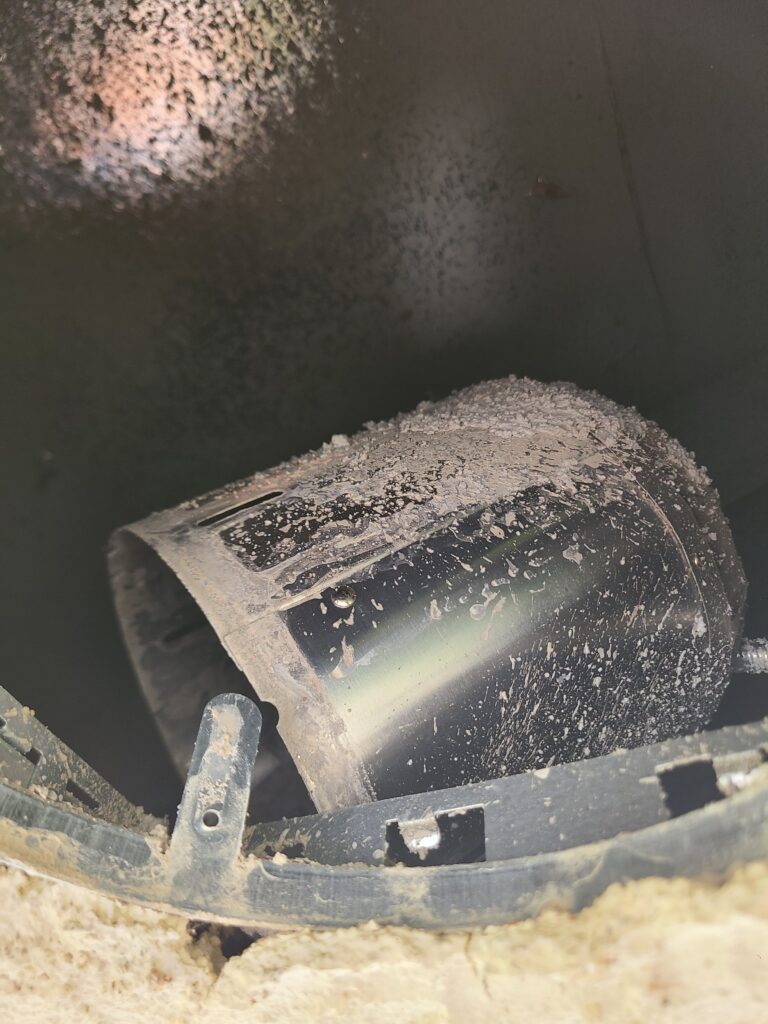
Once you have the can out of the way, you should be able to see the ballast box itself in the ceiling. There will be an armored cable cover running from the end of the can to this box.
Disconnect the Ballast when converting 4-pin CFL to LED
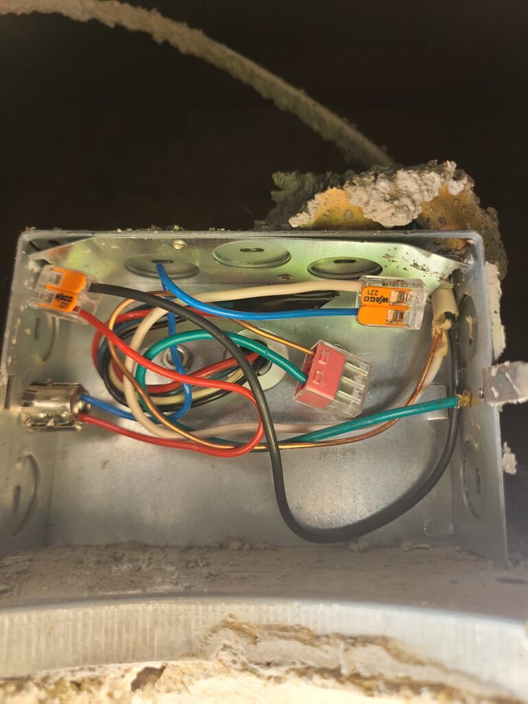
Inside the ballast box, there will be several wires. Disconnect all of the wiring by removing the wire nuts or push in connectors. Disconnect the black (hot) wires first, then the neutral. Leave the ground wire bundle connected. Push this bundle off to the side.
Be very careful when disconnecting the red and blue wires from the ballast. A capacitor with stored energy may be present inside the ballast. The capacitor can also cause a spark when cutting the wires (ask me how I know). To try to avoid this potential hazard, I both wore gloves and then cut the wires short underneath the wire nuts rather than removing the nut first.
Separate the Wires
Once disconnected, separate these wires into three groups:
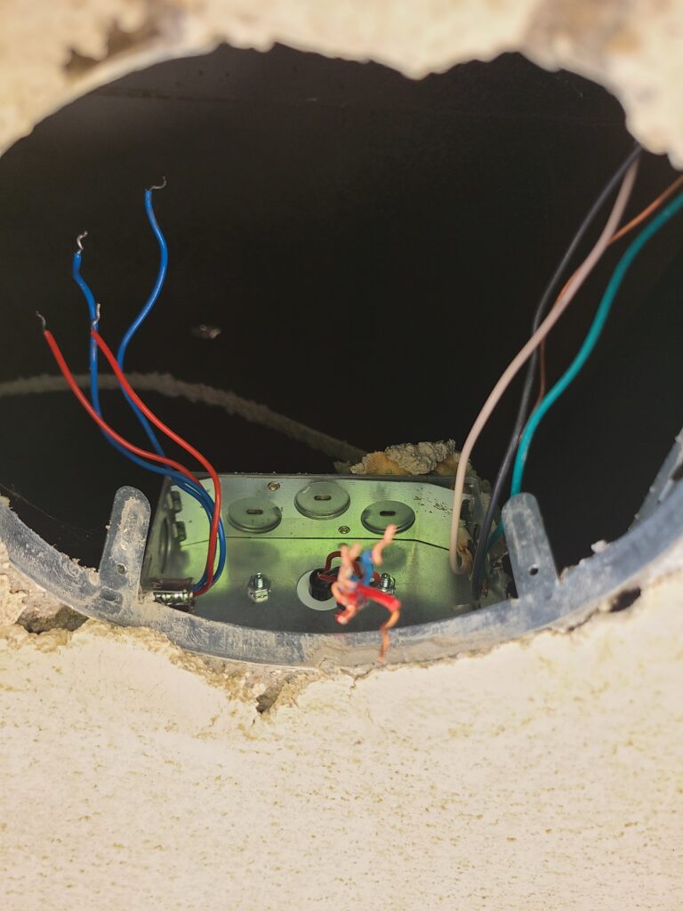
- wires from the can (The red and blue wires going through the armored cable from the ballast box, into the can and the 4-pin socket.)
- wires from the house (The romex cables entering the box, likely 14 gauge / 2 conductors – one black, one white, one ground.)
- wires from the ballast (In my case, these were coming into the center of the box. My ballasts are mounted directly to the back of the box. This bundle is likely two red wires, two blue wires, one white wire, and one black wire.)
Cut all of the wires from the ballast a few inches from the box. Be careful of potential spark hazards as mentioned earlier, in case the ballast capacitor might not have been discharged. Wrap the end of the bundle in electrical tape, and fold it back into the box. Since we are bypassing the ballast, we don’t need to connect it any longer (but we also don’t need to remove it, it can sit in the box disconnected and unused).
Send 120V Line Voltage to the LED
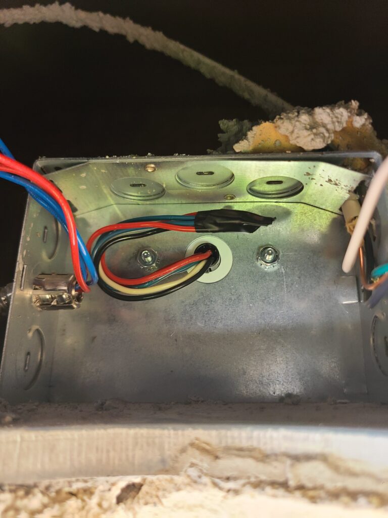
If you did not cut the 4-pin socket wires earlier, bring the can back down far enough that you can do so now. Once you’ve cut the socket, you can remove one of the red wires and one of the blue wires that go from the ballast to the can. We only need two wires in the can to connect to the light, since we’re using the line voltage from the house.
From here, we need to connect those remaining two wires to the wires that come from the electrical panel. I prefer to use Wago 221 Lever Nuts to make these connections, because it’s very easy to see that you have a solid connection.
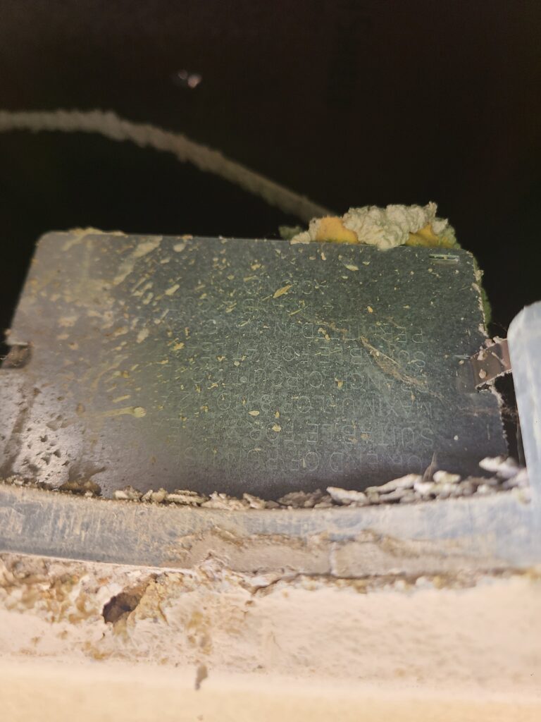
Strip approximately 1/2 inch of insulation from the red and blue wires that remain from the can. Connect the blue wire and any white wires from the house together using a lever nut. Connect the red wire to any black wires that come from the house using a second lever nut. Fold all of the wires neatly back into the box, and put the cover plate back on.
Remount the Can
With the wiring in the ceiling complete and the ballast bypassed, we can now remount the can. Put it back into place, aligning the holes from the mounting screws you removed in the first step, and reattach the mounting screws. Be careful when reseating the can, as the edges are sharp.
I have found that sometimes it’s easier to get the can to seat correctly if you attach one or two of the mounting screws first, then pull down on the other side to line up those holes. Sometimes, if you try to line up all three or four at once, you’ll end up knocking one side out of alignment as you pull down on the other side.
Connect the LED
Strip approximately 1/3 inch of insulation from the red and blue wires inside the can. Attach the male end of a TP24 connector to these two wires, making sure to wire the red wire to the positive side of the TP24. The connector may have the letter B (black), a black stripe, or a + marking on the connector to indicate the positive lead, depending which TP24 you use.
Most retrofit LED kits will come with the female end of this connector already installed on the wiring from the light, so adding the other side to the wiring inside the can will make this extremely easy to connect (and to change out if necessary later).
If your light has a ground wire, you can slightly loosen one of the mounting screws and wrap the ground around the screw. Wrap it around the screw clockwise. This allows the wire to make a good connection when tightening the screw.
Add the Disclaimer Sticker to indicate converting 4-pin CFL to LED
The retrofit light kit you purchased likely came with a disclaimer sticker. This sticker indicates that you have modified the can to be used with LEDs. It alerts future owners not to install a CFL on wiring modified for LEDs.
Secure the LED with the Mounting Springs
After connecting the wiring, use the mounting springs or clips to secure the LED. Squeeze the clips together and slide them into the mounting ears inside the can. This was by far the most annoying thing to accomplish, in my experience. It may take some practice to line everything up right.
Once the clips are inside the ears inside the can, push the light up into the ceiling. You may have to twist a bit to get it to sit flush against the drywall.

